|
What's The Problem?
Anyone who has ever rebuilt a carburetor before knows that setting the float level is a key part of a proper rebuild. They likely also know that measuring and setting the float alignment is far less accurate than checking the fuel level in the float bowl and making incremental adjustments.
To check float bowl fuel levels, the procedure varies from one type of carburetor to another but it usually boils down to essentially the same thing: A fuel level gauge of some kind is attached to the float bowl drain, the drain screw is loosened to open the drain and fuel fills the test gauge (usually a clear tube or hose) to a point that can then be compared to recommended levels.
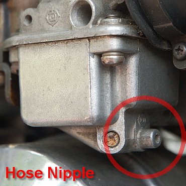
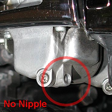
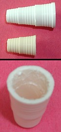
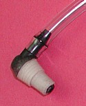
Hitachi carburetors, like the ones found on the 85/86 XJ700 Maxim (non-X), have a hose nipple as part of the float bowl drain of each carburetor. That makes it very easy to attach a hose for the purpose of testing float bowl fuel levels. The Maxim-X Mikuni carbureturs, however, have no such hose nipple on the carburetor drains. All the Mikunis have are holes (no nipple) and no way to attach a hose. The pictures below show a comparison of a Hitachi float bowl drain (left) and a Mikuni float bowl drain (right).
 |
 |
 |
|
|
|
Hitachi Carburetor
85/86 Yamaha XJ700 Maxim |
 |
Mikuni Carburetor
85/86 Yamaha XJ750X Maxim-X |
Yamaha's Fuel Level Gauge
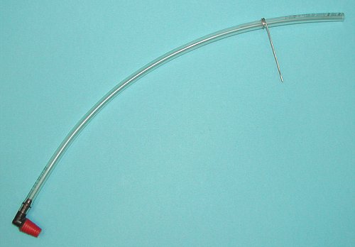
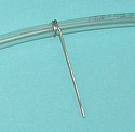
To test the Maxim-X's Mikuni carburetor float bowl fuel levels, Yamaha provides a specialized fuel level gauge of its own, Yamaha Part #: 90890-01312. A picture of the Yamaha fuel level gauge, as shown in the Maxim-X service manual, is shown below.
I'm not entirely sure how the gauge in the picture can be connected to the Maxim-X Mikuni float bowl drains. Unless it's flexible and a necessary fitting isn't shown, the gauge is clearly for a vertical drain with a nipple but the Maxim-X Mikunis have a horizontal drain without a nipple. It looks like the wrong tool to me but that's the one shown in the Maxim-X service manual. Perhaps the orientation in the picture is misleading & certain parts aren't shown. I can't say - I've ever held the real thing. |
 |
If you're so inclined, you can try to buy the Yamaha fuel level gauge but it's no longer listed and hasn't been available for a long time. If you'd rather make your own Mikuni fuel level tester, then you'll find instructions for one possible approach below. I've made several like this and they work well.
How To Make Your Own Gauge
My version of the Fuel Level Gauge is made up of three (3) pieces with an optional fourth piece as follows:
Custom Fuel Level Tester Components
|
 |
|
1.
|
12" length of 1/4" clear hose (minimum length 8")
|
|
2.
|
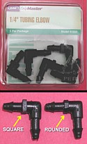
1/4" elbow hose fitting
|
|
3.
|
|
|
4.
|
Paperclip (optional for hose hookup)
|
 |
|
Finding a length of clear hose is a snap and finding the DAP Kwik Seal cap is equally easy but finding the elbow fitting was a little more difficult. For some reason, quarter inch 90° elbow hose fittings aren't as plentiful as you might think. Even plumbing supply stores in my area didn't carry anything that small. Not even Canadian Tire had ¼" sizes (which I would have expected in connection to windshield washer pumps and hoses). After much searching, I found an appropriate hose fitting at Home Depot in a section of the store dedicated to refrigerator electrical & plumbing components. Apparently ¼" elbow house fittings are needed often for the water supplies of refrigerators equipped with ice cube makers. Even so, they weren't carried at every Home Depot I visited nor any other stores where I would have expected them. Finding this simple component was the most difficult part of the entire job (isn't it always?) but once you have it, you're ready to start.
|
Step 1 - Prepare Cap
Remove the cap from the tube of DAP Kwik Seal sealant and discard the tube (or use it up somewhere around the house if you like  ). The stuff only costs about CAD $1.50 so it won't be a big loss. As you might imagine, the cap isn't exactly perfect for the job - it's just the most suitable thing I could find. To use it for this application, a number of things have to happen to it. First, a hole has to be drilled in the closed tip of the cap to allow one end of the elbow hose fitting to protrude through the cap. Second, the cap will need to be shortened to match the length of one leg of the elbow fitting. With a utility knife, cut away sufficient material from the open end of the soft plastic cap until an end of the elbow fitting protrudes just barely through the hole you drilled in the cap. Third, it will be necessary to roughen up the inner surface of the cap. In the end, the elbow must be fastened to the cap somehow but if the cap's inner surface is left as smooth as it is, the two parts will likely separate. What I found easiest and most effective was cutting a crisscross pattern of grooves into the soft plastic using my utility knife. Once you've roughened the inner surface sufficiently (don't hold back), the cap is ready for the next step. ). The stuff only costs about CAD $1.50 so it won't be a big loss. As you might imagine, the cap isn't exactly perfect for the job - it's just the most suitable thing I could find. To use it for this application, a number of things have to happen to it. First, a hole has to be drilled in the closed tip of the cap to allow one end of the elbow hose fitting to protrude through the cap. Second, the cap will need to be shortened to match the length of one leg of the elbow fitting. With a utility knife, cut away sufficient material from the open end of the soft plastic cap until an end of the elbow fitting protrudes just barely through the hole you drilled in the cap. Third, it will be necessary to roughen up the inner surface of the cap. In the end, the elbow must be fastened to the cap somehow but if the cap's inner surface is left as smooth as it is, the two parts will likely separate. What I found easiest and most effective was cutting a crisscross pattern of grooves into the soft plastic using my utility knife. Once you've roughened the inner surface sufficiently (don't hold back), the cap is ready for the next step.
|
 |
|
Step 2 - Prepare Elbow
If the elbow hose fitting you were able to source is like the one I found, then it may have a wider, possibly square, section in the middle where the two arms of the elbow connect. In my case, the built up square section in the middle prevented the elbow fitting from fitting snuggly into the cap - the square section was too wide for the open end. I had to grind the square section down until it was small enough to fit into the open end of the cap. In most cases, this probably won't be necessary but if it is, it's a fairly simple matter to grind it to size before moving on to the next step.
|
 |
|
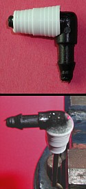
Step 3 - Fasten Cap to Elbow
As I mentioned in the first step, the elbow hose fitting has to be fastened securely to the plastic cap. You can do this by inserting one end of the elbow into the open end of the cap (the wide end) so that one end of the elbow protrudes through the hole you drilled in the other end of the cap. Fill the space in the cap surrounding the elbow with a 5-Minute Epoxy of your choosing and wait for it to set. In my case, I had some epoxy leak out the drilled hole past the elbow and it actually ended up partly clogging the elbow so it might be wise to do something like I did for my second attempt. Cut off a short length of a metal coat hanger and insert it into the end of the elbow which is protruding through the hole drilled in the cap. For the elbow fitting I found, the coat hanger fit and sealed the end of the elbow perfectly and I used the coat hanger to support the assembly in a vise while I filled in the epoxy and allowed it to set. The crisscross pattern of grooves in the inner surface of the cap serves to anchor the epoxy to the cap so it won't spin or pull off during use.
|
 |
|
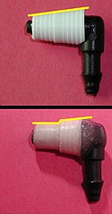
Step 4 - Resize Cap
In a perfect world, the cap would simply fit into the Mikuni float bowl drain hole as is but tragically that's not the case. I couldn't find anything that would fit the drain hole perfectly despite many hours of trying. I eventually settled on the soft plastic cap because I knew it wouldn't be difficult to whittle and sand it down to an appropriate size for the float bowl drain... and that's what I did. To save some time, I first reduced the diameter of the cap assembly by whittling away the bulk of the material that would be removed. As the diameter got closer to what it needed to be, I rounded the whittled down end by spinning it in a folded piece of 100 Grit sandpaper. Once it was rounded again and close to the right diameter, I switched to 220 Grit sandpaper and continued sanding and intermittently testing the fit in the drain hole. I was satisfied with the fit when the tip could be spun snuggly into the drain hole to a depth of about 6mm (¼"). I didn't want the assembly to slip in easily because that would inevitably lead to leaks so I left it a tiny bit larger than the hole and achieved the final fit by essentially screwing the assembly into the drain hole which pressed the soft plastic into both the right shape and size for a fuel-tight seal (not that a fuel tight seal is very important because you'll be getting your fingers wet anyway when it's removed from each drain hole -reasonably fuel tight would have been plenty).
|
 |
|
Step 5 - Attach Hose
The final step is attaching the hose to the fitting assembly which I'm sure doesn't require any more instructions .
|
 |
|
Step 6 - Optional
Since I'm always documenting the work I do on my Maxim-X, it was necessary to find a way to hookup the fuel level gauge when in use so I could take a picture or two. To make the hookup possible, I straightened a simple paperclip and then wound it around the hose just tightly enough that it could still be moved but wouldn't move on its own. The paperclip could then be used to hook the hose to something to keep the end in the air while it was still full of fuel. It's not likely that too many people will find this useful but I thought I'd mention it for the people who will inevitably ask, "What's the wire there for?". Now you know.
|
 |
As I mentioned, I've made several of these already (6 to be precise). The prototype (used with moderate success by Dwayne V. & Joe D.) wasn't perfect but it was constructed essentially the same way. The only problem with it was that I didn't reduce the diameter of the inserted portion of the tip enough so it would fit into the float bowl drain hole properly which meant it leaked and had to be held in place too. For the next one, I reduced the tip diameter more so that I ended up with a perfect fit and it seemed to work well... as did the following four.
This is by no means the only way to make a Float Bowl Fuel Level Gauge - it's just one way that I've had success with and that I thought would be reasonably easy to make. If I ever find a better way to make one, I'll naturally post all the details. Meanwhile, I hope these instructions are helpful.
|